1. Introduction to POM (Polyoxymethylene)
POM, commonly known by the brand name Delrin® (a homopolymer), is an engineering thermoplastic renowned for its high stiffness, low friction, excellent dimensional stability, and good chemical resistance. These properties make it an ideal material for precision gears, especially in applications where lubrication is undesirable or where quiet operation is needed.
2. CNC Machining Processes for POM Gears
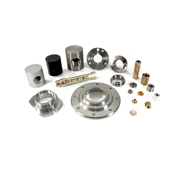
While gears can be injection molded for high volumes, CNC machining is preferred for prototypes, low-volume production, or highly customized designs. The primary CNC methods are:
A. CNC Milling:
- Process: A multi-axis (3-axis, 4-axis, or 5-axis) CNC mill uses rotating end mills to cut the gear blank into the desired shape. The tool paths are programmed (using CAM software) to accurately create the tooth profile, hub, and other features.
- Suitability: Best for spur gears, helical gears, bevel gears, and custom gear profiles. It is highly flexible for one-off parts.
B. CNC Turning:
- Process: A CNC lathe rotates the material while a stationary cutting tool shapes it. This is used primarily for creating the cylindrical gear blank, machining the bore (hole), and facing the sides.
- Suitability: Used for the initial stages of gear manufacturing. The actual gear teeth are almost always cut using milling or hobbing on a CNC mill or a dedicated gear hobbing machine.
C. CNC Gear Hobbing:
- Process: This is a specialized machining process where a cutting tool called a “hob” – which is itself a helical gear with gashes that form cutting edges – meshes with the gear blank and cuts the teeth into it. Modern gear hobbing machines are CNC-controlled for high precision.
- Suitability: The most efficient and accurate method for producing high-quality spur and helical gears in small to medium batches.
Typical CNC Machining Workflow for a POM Gear:
- Material Selection & Preparation: Select the appropriate POM grade (e.g., homopolymer for high stiffness, copolymer for better chemical/thermal stability). The material is supplied as rods or plates.
- CAD Model Creation: A 3D model of the gear is designed, specifying the critical parameters: number of teeth, module/pitch, pressure angle, helix angle, face width, etc.
- CAM Programming: The CAD model is imported into CAM software, where tool paths, cutting speeds, feed rates, and depth of cut are defined.
- Fixturing: The POM rod or blank is securely clamped onto the CNC machine’s worktable.
- Machining:
- Step 1 (Turning): The outer diameter and bore are machined to precise dimensions.
- Step 2 (Milling/Hobbing): The gear teeth are cut. For complex gears, 4th or 5th-axis milling is used to index the blank and cut each tooth profile accurately.
- Deburring & Finishing: Any small burrs or sharp edges left from machining are carefully removed by hand or with fine abrasives to ensure smooth meshing.
- Inspection: The final gear is inspected using calipers, micrometers, and possibly a Coordinate Measuring Machine (CMM) or a gear measuring machine to verify all critical dimensions against the drawing.
3. Key Considerations and Best Practices
Machining POM is generally straightforward, but attention to detail is critical for achieving high-performance gears.
- 1. Heat Management:
- Challenge: POM has a relatively low melting point (~175°C). Excessive heat from machining can cause the material to soften, leading to deformed teeth or a poor surface finish.
- Solution: Use sharp, polished cutting tools (typically uncoated carbide or high-speed steel). Employ compressed air for cooling instead of coolant. Coolant can be used but may cause swelling in some POM grades; if used, it must be completely removed afterward.
- 2. Tool Geometry and Sharpness:
- Use tools with positive rake angles and sharp edges for clean, shear-based cuts. Dull tools generate more heat and produce tearing, compromising the gear tooth accuracy.
- 3. Avoiding Internal Stresses:
- POM can have internal stresses from the manufacturing process of the raw stock. Stress-relieving the material before final precision machining (by annealing) can prevent subsequent warping.
- 4. Hygroscopic Nature:
- POM absorbs moisture from the air. While much less hygroscopic than nylon, it’s good practice to store the material in a dry environment and machine it in a controlled atmosphere to maintain dimensional stability.
- 5. Chip Control:
- POM produces long, stringy chips that can wrap around the tool and workpiece. Proper chip evacuation is crucial. Use tools with good flute geometry and programmed pecking cycles to break chips.
- 6. Dimensional Tolerance:
- POM has a low coefficient of thermal expansion, which is beneficial for dimensional stability. However, machinists must account for its slight elasticity (spring-back) during cutting to hold tight tolerances, especially on the tooth profile.
4. International Standards vs. European / American Standards for Gears
Gear design and inspection are governed by standards to ensure interoperability and performance. The main distinction is between the ISO (International) system and the AGMA (American Gear Manufacturers Association) system. DIN (German Institute for Standardization) standards are very influential in Europe and are largely aligned with or form the basis for ISO standards.
| Feature | International Standards (ISO) | European / American Standards (AGMA / DIN) |
|---|---|---|
| Primary Organization | International Organization for Standardization (ISO) | AGMA (North America), DIN (Germany, widely used in EU) |
| Key Standards | ISO 53: Standard tooth proportions. ISO 1328-1: Definitions and allowable values for deviations on cylindrical gears. ISO 4156: Straight cylindrical involute splines. | AGMA 2002: Tooth proportions, tolerances for cylindrical gears. AGMA 2015: Accuracy classification. DIN 3960-3967 series: Definitions, tolerances for cylindrical gears. |
| Module vs. Diametral Pitch | Uses Module (m) in millimeters.m = Pitch Diameter (mm) / Number of Teeth | Uses Diametral Pitch (DP) in inches.DP = Number of Teeth / Pitch Diameter (inches)Note: Module = 25.4 / Diametral Pitch |
| Pressure Angle | Commonly 20°. Also 14.5° and 25° exist but 20° is the modern standard. | Commonly 20° (modern). 14.5° and 25° are also specified, especially in older AGMA standards. 20° is now dominant. |
| Tolerance Classification | Uses accuracy grades (e.g., ISO 1328 defines grades 1-12, with 1 being the most precise and 12 the least). A gear might be specified as “ISO 1328 Class 7”. | AGMA uses quality numbers (e.g., AGMA Q10 is less precise, Q3 is very precise). DIN uses quality grades (e.g., DIN Class 5, 6, 7, etc.), which are closely related to ISO grades. |
| Philosophy | A globally harmonized system, increasingly adopted worldwide. Tends to be very comprehensive and detailed. | AGMA standards are deeply entrenched in North American industry. DIN standards are known for their rigor and are the historical basis for many ISO standards. |
Practical Implication for Your POM Gear Drawing:
When designing and specifying your CNC-machined POM gear, you must choose a standard and state it clearly on the technical drawing. For example:
- Using ISO: You would specify the Module (e.g., 1.5), Pressure Angle (e.g., 20°), and Tolerance Class (e.g., ISO 1328 Class 8).
- Using AGMA: You would specify the Diametral Pitch (e.g., 16 DP), Pressure Angle (e.g., 20°), and Quality Number (e.g., AGMA Q9).
For most new designs, especially for global markets, the ISO system (using Module) is the recommended starting point.