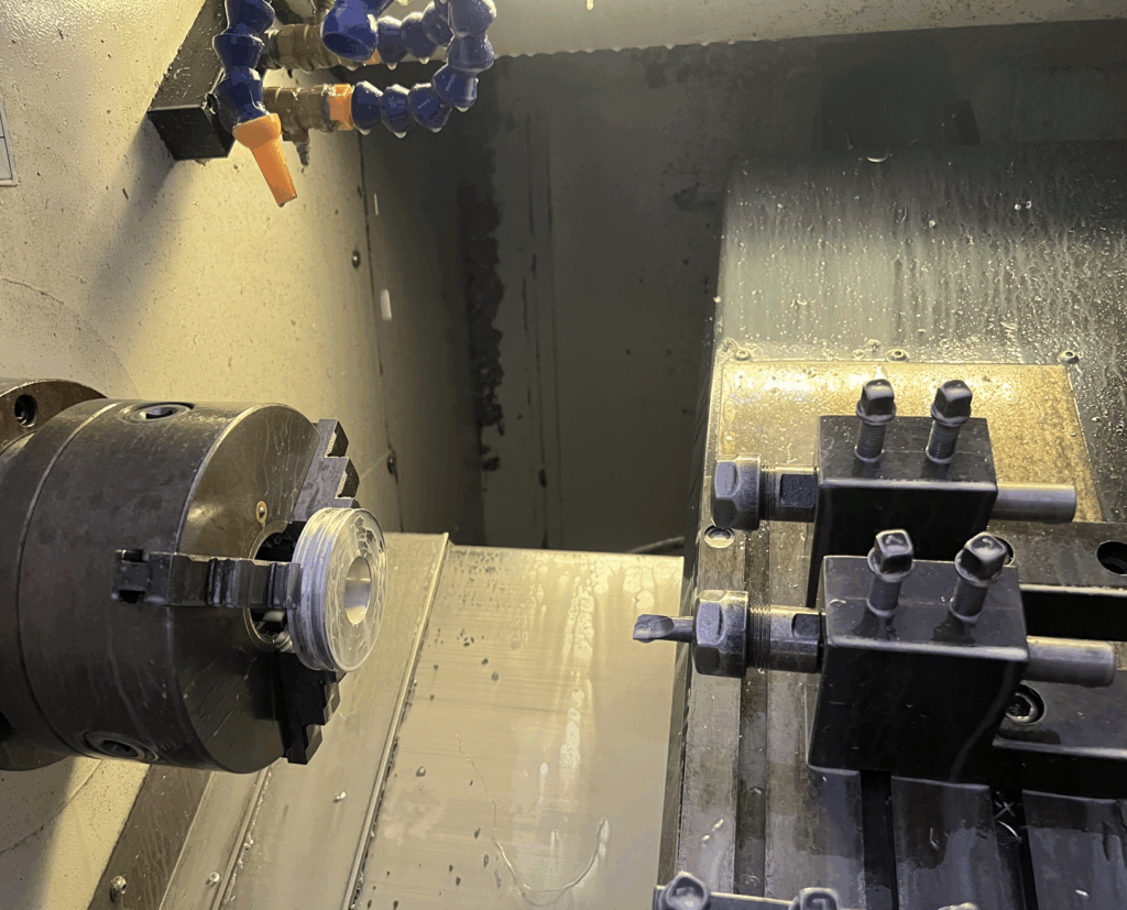
In China’s CNC machining industry, most suppliers offer competitive precision capabilities, particularly for small to medium-sized parts. However, certain geometric constraints—such as large-area thin-walled structures—pose significant challenges in maintaining tight tolerances and flatness across multiple points. Below is a detailed breakdown of standard achievable tolerances and the specific limitations under demanding conditions.
1. Dimensional Tolerances
- General Machining (Metals & Plastics):
- Metals (Aluminum, Steel, Stainless Steel, Brass):
- Standard: ±0.05 mm to ±0.1 mm
- High Precision: ±0.02 mm to ±0.05 mm (with fine-tuned processes and inspection)
- Plastics (ABS, PC, Nylon, POM, etc.):
- Standard: ±0.1 mm to ±0.2 mm (subject to material stability and tooling strategy)
- High Precision: ±0.05 mm possible for stable engineering plastics
- Metals (Aluminum, Steel, Stainless Steel, Brass):
- Hole & Shaft Tolerances:
- Standard Holes: H7/H8 grades achievable (±0.02–0.04 mm)
- Press-fit Features: ±0.01–0.02 mm possible with secondary finishing
2. Flatness & Surface Parallelism/Perpendicularity
- Flatness:
- General Milling: 0.05–0.1 mm per 100 mm span
- Precision Grinding/Scraping: 0.01–0.02 mm per 100 mm
- Parallelism/Perpendicularity:
- Between machined faces: 0.02–0.05 mm per 100 mm
- Between hole axes and surfaces: 0.03–0.08 mm per 100 mm
3. Geometric (Form & Position) Tolerances
- Circularity (Roundness): 0.01–0.03 mm for turned/milled features
- Cylindricity: 0.02–0.05 mm
- Position Tolerance:
- Standard: ±0.05–0.1 mm (for hole patterns, pins, etc.)
- High Precision: ±0.02 mm with CNC probing and optimized setups
- True Position (GD&T): 0.05–0.1 mm diameter zone typical; 0.02–0.05 mm achievable with careful process control
Key Factors Influencing Tolerance Achievement
- Machine Tool Capability:
- Entry-level CNC mills: ±0.1 mm typical
- High-end 3/4/5-axis machines (DMG Mori, Haas, etc.): ±0.02–0.05 mm
- Material Stability:
- Metals (especially aluminum) are more stable than plastics
- Thermal expansion and stress relief affect final dimensions
- Tooling & Fixturing:
- Dedicated fixtures improve repeatability
- Thin parts require specialized support to avoid vibration
- Operator & Programming Skill:
- Experienced programmers optimize tool paths for accuracy
- In-process measurement and compensation enhance results
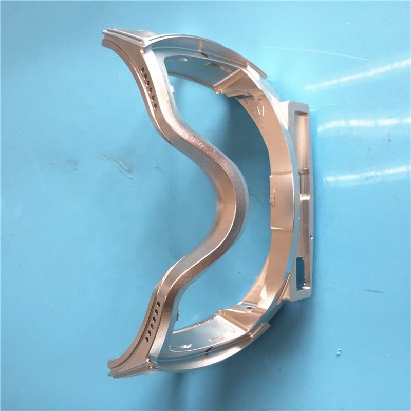
Limitations: Large-Area Thin-Wall Structures
Scenario Definition
- Large-Area Thin-Wall:
- Example: 300 mm × 300 mm part with 1–2 mm wall thickness
- Or: 500 mm × 200 mm panel with 1.5 mm uniform thickness
- High-Requirement Multi-Point Measurements:
- Flatness requirement: ≤0.1 mm across entire surface
- Multiple location-specific dimensional tolerances: ±0.05 mm at 10+ points
Why These Requirements Are Difficult to Guarantee
- Material Distortion & Stress:
- Residual stress from raw material (plate/block) releases during machining, causing warping
- Thin sections lack rigidity to resist cutting forces and clamping pressures
- Thermal Effects:
- Machining generates heat; uneven thermal expansion distorts thin geometries
- Cooling/flood coolant may not fully stabilize temperature gradients
- Fixturing Challenges:
- Clamping thin parts without inducing distortion is extremely difficult
- Vacuum tables help but may not fully restrain large flexible parts
- Tool Deflection & Vibration:
- Long tool extensions required for deep pockets increase deflection
- Chatter marks and poor surface finish affect flatness measurements
- Post-Machining Springback:
- Parts may warp after unclamping due to stress redistribution
- This is unpredictable and varies batch-to-batch
Typical Outcomes for Such Designs
- Flatness Deviation: 0.2–0.5 mm over 300 mm span (vs. desired 0.1 mm)
- Point-to-Point Dimensional Variation: ±0.1–0.3 mm (vs. desired ±0.05 mm)
- Surface Waviness: Visible undulations due to tool deflection and vibration
- Risk of Cracking/Deformation: Especially in corners or near clamped areas
Supplier Recommendations for Demanding Geometries
- Design Stage Consultation:
- Engage suppliers early for DFM (Design for Manufacturing) feedback
- Consider adding ribs, gussets, or gradual thickness transitions
- Alternative Manufacturing Strategies:
- Segment large parts into smaller components assembled post-machining
- Use stress-relieved or pre-machined stock material
- Post-Processing Compensation:
- Stress relief annealing before final finishing passes
- Manual correction/shimming may be needed for flatness
- Inspection & Acceptance:
- Clearly define critical tolerance zones on drawings
- Use statistical sampling rather than 100% point inspection
- Agree on measurement methods (CMM vs. manual height gauge)
Summary Table: Capabilities vs. Limitations
| Aspect | Standard Achievable | Large Thin-Wall Challenge |
|---|---|---|
| Dimensional Tolerance | ±0.05–0.1 mm (metal) | ±0.1–0.3 mm (scattered points) |
| Flatness (per 300 mm) | 0.05–0.15 mm (with grinding) | 0.2–0.5 mm (often out of spec) |
| Position Tolerance | ±0.05–0.1 mm | ±0.1–0.2 mm (requires compensation) |
| Surface Finish (Ra) | 1.6–3.2 µm typical | 3.2–6.3 µm due to vibration |
| Process Stability | High for robust geometries | Low; requires iterative tryout and adjustment |
Conclusion
While Chinese CNC suppliers are capable of delivering high-precision parts for most applications, large-area thin-wall components with tight multi-point tolerances and flatness requirements remain a significant challenge. Success in such projects depends on:
- Collaborative design optimization
- Specialized process planning (including roughing, stress relief, and finishing stages)
- Realistic tolerance expectations and acceptance criteria
It is strongly advised to prototype and validate before committing to production quantities for such critical geometries.