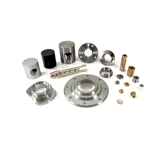
Quality inspection is a critical phase in the CNC machining process, ensuring that manufactured parts conform precisely to design specifications, dimensional tolerances, and surface finish requirements. The process leverages a combination of tools, from simple hand-held devices to advanced computer-controlled systems.
Part 1: Quality Inspection Equipment
The equipment used varies based on the required precision, the complexity of the part, and the stage of inspection.
1. Basic Hand Tools (For First-Line Inspection):
- Calipers (Vernier, Dial, or Digital): The most common tool for quick measurements of external and internal dimensions, and depths.
- Micrometers: Offer higher precision than calipers for measuring thicknesses, diameters, and other small features.
- Dial Indicators: Used to measure slight variations, such as runout (wobble) of a rotating part, flatness, and alignment.
- Gauge Blocks and Pin Gauges: Known as “standards,” they are used for tool calibration or for direct Go/No-Go checks of specific hole sizes or dimensions.
2. Precision Surface Plates and Height Gauges:
- A granite Surface Plate provides an ultra-flat reference surface.
- A Height Gauge is used on this plate to accurately measure vertical dimensions and to scribe lines for layout inspection.
3. Optical Comparators / Profile Projectors:
- These machines project a magnified shadow of a part onto a screen. The shadow is compared against a transparent chart (Mylar) of the part’s ideal profile, allowing for fast and accurate inspection of complex 2D contours and geometries.
4. Coordinate Measuring Machine (CMM):
- This is the industry standard for high-precision, comprehensive inspection. A CMM uses a touch-trigger probe (or laser/scanner) to measure discrete points on a part’s surface.
- How it works: The part is placed on the CMM’s table. The probe moves along three axes (X, Y, Z) and records the coordinates of each point it touches.
- Software Analysis: The collected point cloud data is compared directly to the original CAD model. The software generates a detailed report showing deviations with color maps, making it easy to see where the part is out of tolerance.
5. Advanced Non-Contact Scanners:
- Laser Scanners: Capture millions of data points very quickly by projecting a laser line onto the part.
- Structured Light Scanners: Project a pattern of light onto the part and use cameras to capture the distortion, creating a highly accurate 3D “point cloud.”
- Like CMMs, this data is compared to the CAD model for comprehensive analysis. They are ideal for complex free-form surfaces.
6. Surface Roughness Testers:
- A specialized instrument with a diamond-tipped stylus that traces across the part’s surface. It quantitatively measures surface texture parameters like Ra (Average Roughness) or Rz (Mean Roughness Depth) to ensure it meets specifications.
7. Hardness Testers (Rockwell, Brinell, Vickers):
- Used to verify the material hardness of a part, especially after heat treatment processes. This is a key test for functional components requiring wear resistance.
Part 2: Detailed Quality Inspection Steps
The inspection process is a systematic workflow that can occur at different stages.
Step 1: First Article Inspection (FAI)
This is the most critical inspection, performed on the first part off the machine after a new program is set up.
- In-Process Checks (by the Machinist): The machinist uses hand tools (calipers, micrometers) to perform a preliminary check of key dimensions while the part is still clamped in the vise or fixture. This allows for immediate adjustments to tool offsets if necessary.
- Detailed FAI Report: The part is then taken to the quality lab for a full inspection against all dimensions on the engineering drawing. This is typically done using a CMM or 3D Scanner to ensure 100% dimensional compliance before a production run begins.
Step 2: In-Process Inspection (During Production Run)
For long production runs, periodic checks are conducted to detect tool wear or other process drift.
- Frequency: This could be after every 10th, 50th, or 100th part, depending on the part’s criticality and process stability.
- Method: The operator will typically check the most critical dimensions and features using hand tools or a dedicated fixture.
Step 3: Final Inspection (Before Shipment)
This is the last verification before the parts are shipped to the customer.
- Visual Inspection: The inspector looks for cosmetic defects like scratches, dings, burrs, or tool marks. Any sharp edges are deburred as required.
- Surface Finish Verification: A surface roughness tester may be used to confirm the Ra value meets the print callout.
- Dimensional Spot-Check: Even if a full FAI was done, critical dimensions are often spot-checked again on a sampling of parts from the final batch.
- Documentation Review: The inspector ensures all required documentation, such as material certifications and inspection reports, is complete and accurate.
Step 4: The Digital Workflow (Using CMM/3D Scanner)
The detailed steps for a modern digital inspection are as follows:
- Programming: An inspection program is created offline using the original CAD model. This program defines the points and features to be measured.
- Setup: The part is securely fixtured on the CMM or scanner table. For a CMM, the probe is qualified to define its exact size and position.
- Alignment: The part is aligned to the machine’s coordinate system. This is done by measuring datum features (e.g., a flat plane, a center hole) to establish the part’s X, Y, and Z zero points, just as the CNC machine did during machining.
- Automated Measurement: The CMM or scanner executes the pre-programmed routine, automatically collecting data from all specified features.
- Data Analysis & Reporting: The software compares the measured data to the CAD model’s nominal values. It generates a comprehensive report, typically featuring:
- A color-map deviation chart superimposed on the CAD model (green = in tolerance, red/blue = out of tolerance).
- A data table listing each measured feature, its nominal value, actual measured value, and the deviation.
- A Pass/Fail summary.
Summary
The goal of quality inspection in CNC machining is to ensure conformance to specifications and process control. The industry uses a tiered approach, from quick manual checks for process control to highly accurate, data-driven CMM inspections for validation. This rigorous process guarantees that CNC machined parts are precise, reliable, and fit for their intended purpose.